- Precision in Electrochemistry
- English
Setting up the ZENNIUM hardware
Activate the Targerting and advertising Cookies from the cookies preferences to open the video.
Front panel of ZENNIUM potentiostats
Activate the Targerting and advertising Cookies from the cookies preferences to open the video.
Back panel of ZENNIUM potentiostats
1 Introduction to ZENNIUM series potentiostats
The ZENNIUM series contains 3 potentiostats.
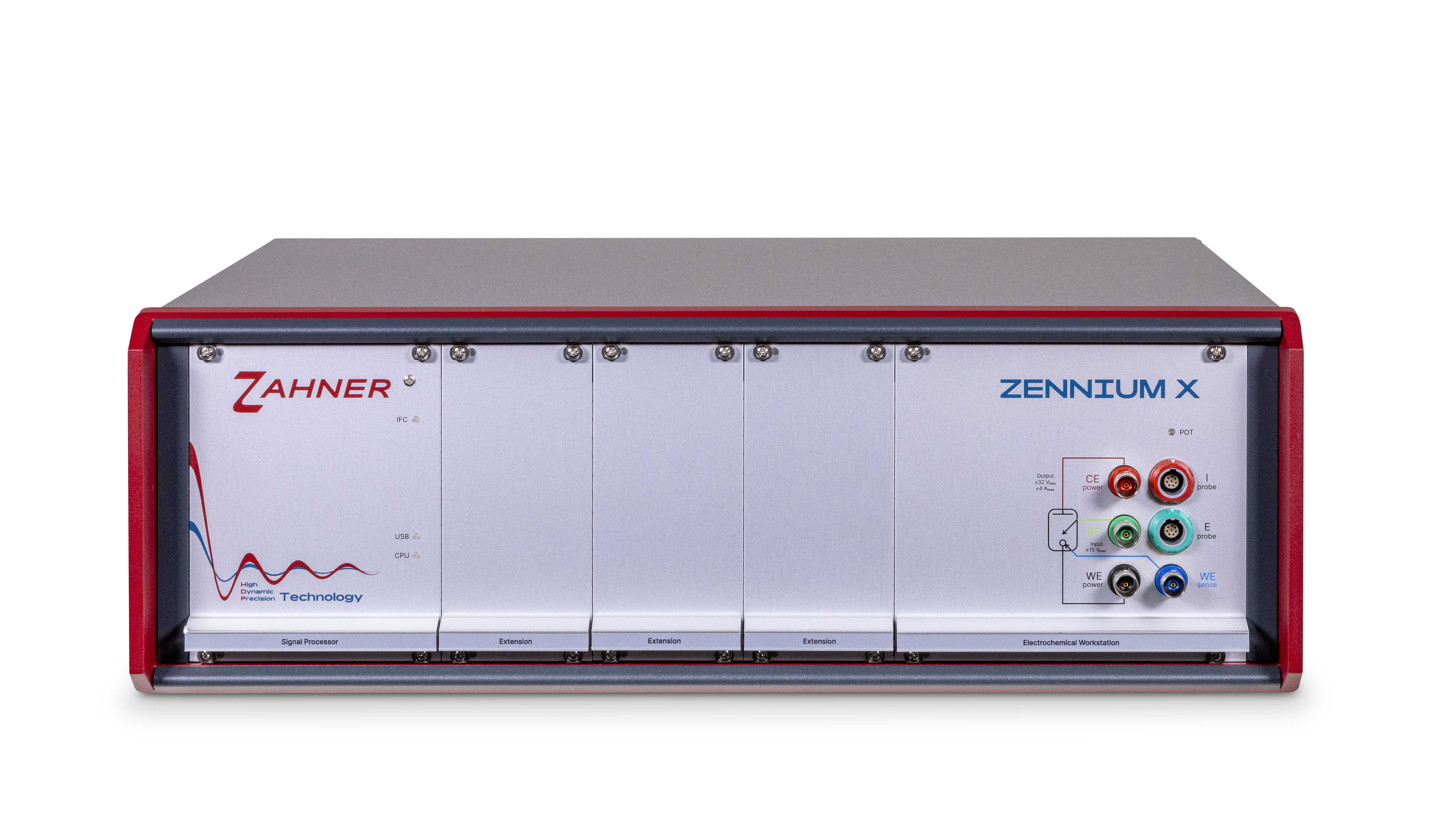
ZENNIUM X
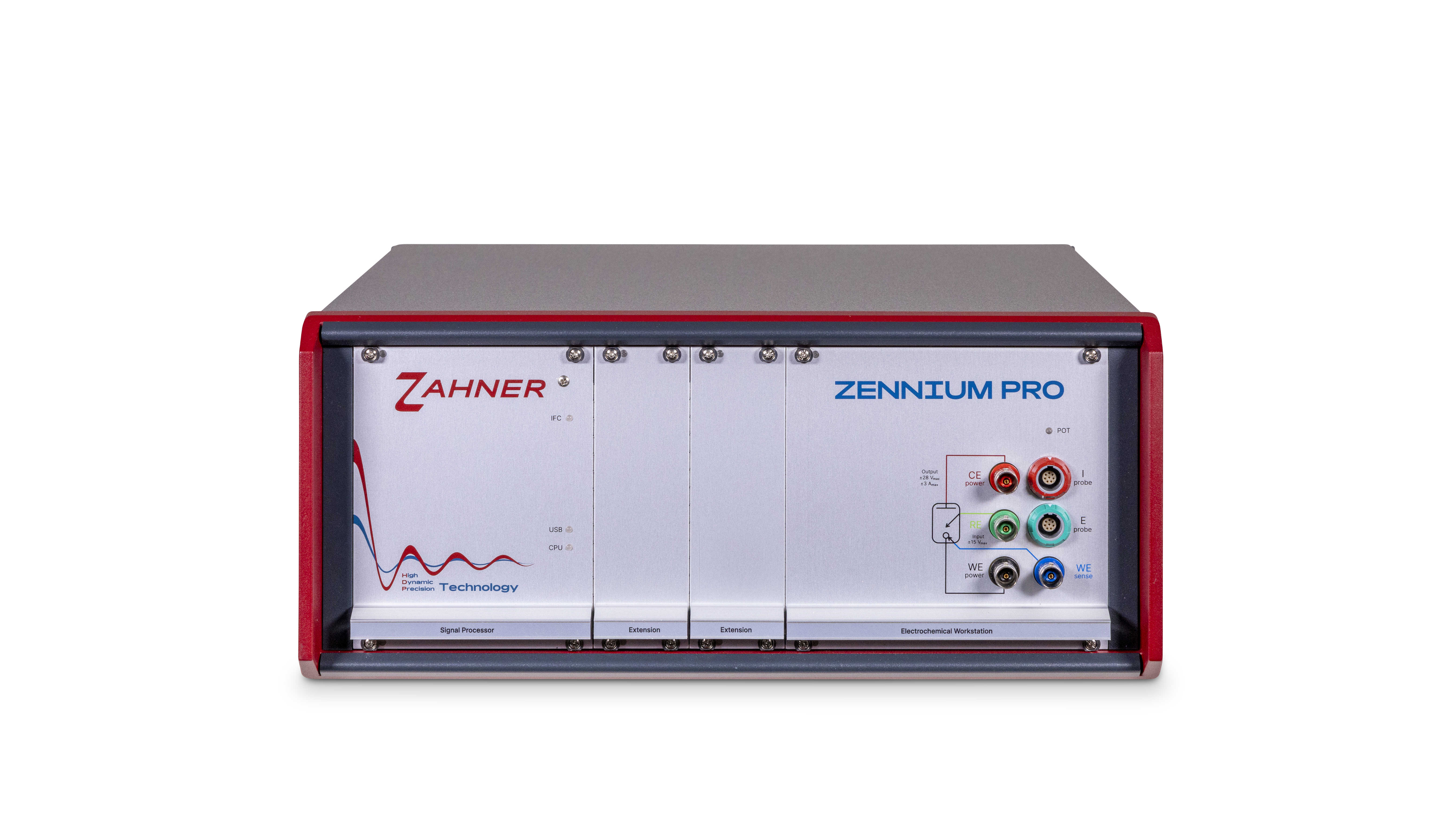
ZENNIUM Pro
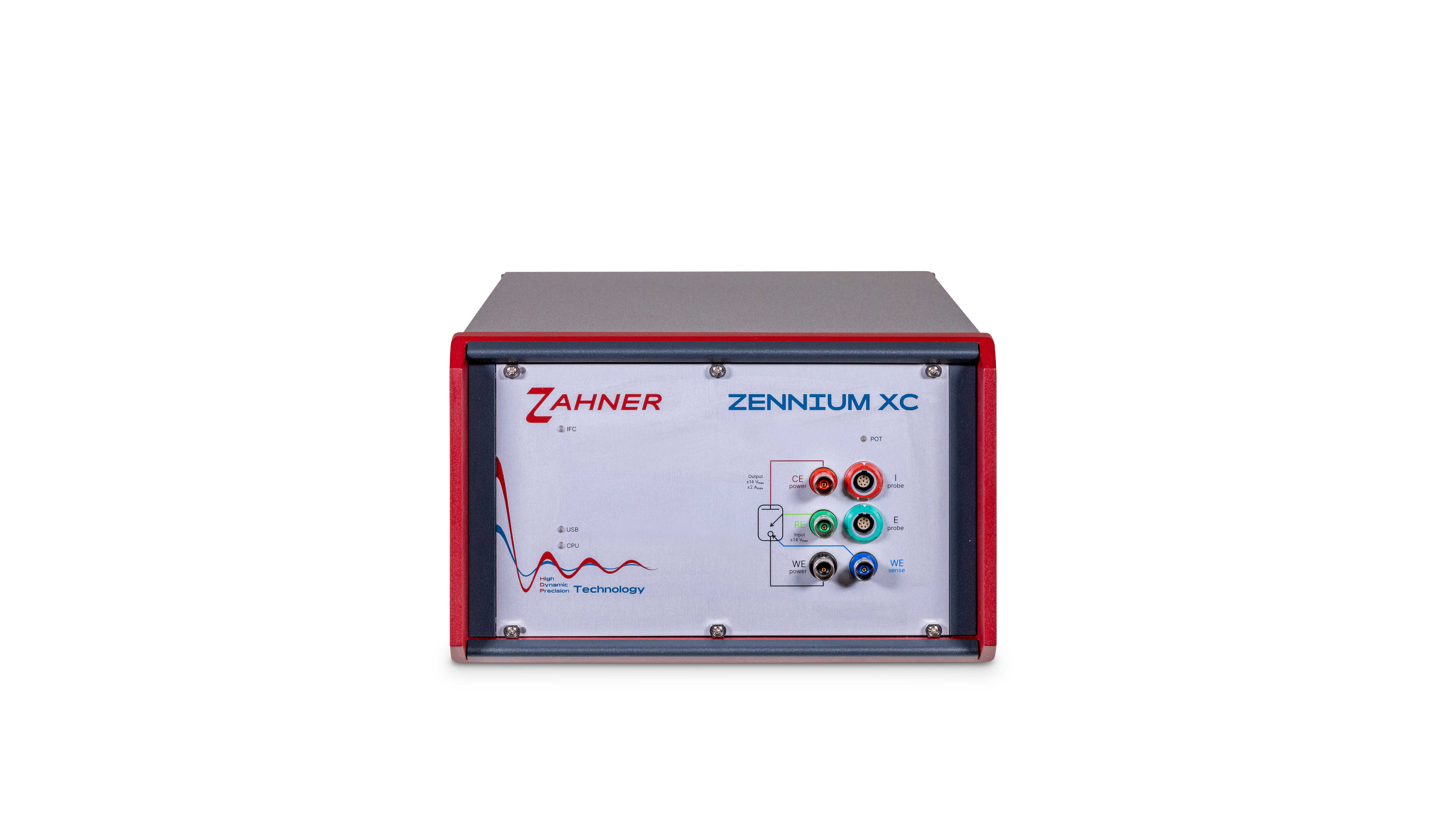
ZENNIUM XC
Fig. 1: Main ZENNIUM series potentiostats (ZENNIUM X, ZENNIUM Pro, and ZENNIUM XC)
The ZENNIUM series potentiostats have different current/voltage ranges and extension possibilities. The main specifications of the ZENNIUM potentiostats are summarized in Table. 1.
| ZENNIUM X | ZENNIUM Pro | ZENNIUM XC | |
|---|---|---|---|
| Current range | Up to ± 4 A | Up to ± 3 A | Up to ± 2 A |
| Voltage range | ± 5 V / ± 15 V | ± 5 V / ± 15 V | ± 5 V / ± 14 V |
| Frequency range | 10 µHz - 12 MHz | 10 µHz - 8 MHz | 10 µHz - 5 MHz |
| Extension slots | 10 | 5 | n.a. |
| Max. parallel channels | 17 | 5 | n.a. |
*An extended specification list for each potentiostat is provided on their respective website pages: ZENNIUM potentiostats.
The Zahner’s potentiostats consume, produce, and radiate electric energy. Improper installation may cause electric disturbances on radio transmitters and receivers. Vice versa, strong emitters of electric fields may cause noise and artefacts to the potentiostat measurements.
1.1 Front panel
The image below shows the front panel of the ZENNIUM series potentiostat.
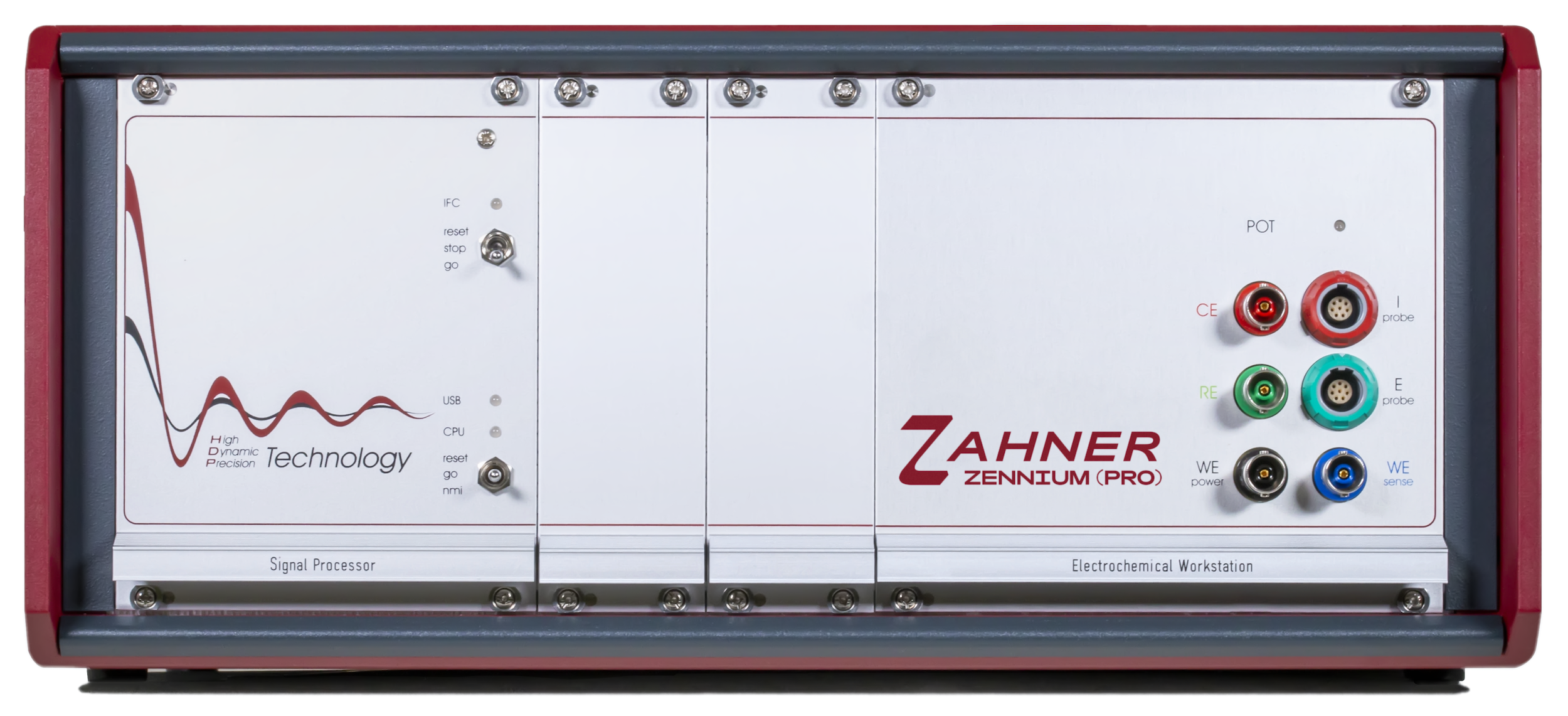
Fig. 2: Front panel of ZENNIUM Pro potentiostat.
On the left side of the ZENNIUM potentiostat, a signal processor is installed. This section also contains three LEDs, 1) IFC, 2) USB, and 3) CPU LEDs which indicate the status of the potentiostat.
Fig. 2: Front panel of ZENNIUM Pro potentiostat.
In the middle, extension slots for Addon Cards are available. If the ZENNIUM series potentiostat is ordered with the add-on cards then the add-on cards come already installed. Add-on cards are required to extend the capabilities of the ZENNIUM potentiostats. ZENNIUM XC is Zahner’s compact potentiostat and does not have an extension possibility. Hence there are no extension slots available in the ZENNIUM XC.
On the right side of the front panel, 4 BNC connectors are present. These BNC connectors, specified below, are connected to their respective electrodes of electrochemical cell or device under test (DUT) via the cell cables.
- Working electrode (WE)
- Working electrode sense (WE sense)
- Reference electrode (RE)
- Counter electrode (CE)
Zahner offers special probes for dedicated experiments (i.e., low impedance measurements, high impedance measurements, or FRA-Probe). I probe and E probe connections on the front panel of the potentiostat are used to connect the potentiostat with Zahner’s probe which then connects to the DUT.
The user must never simultaneously connect the BNC connectors and the I/E probe. If the BNC connectors are used then the I/E probe connections must be left unconnected or vice versa.
Green: If the LED is green then the potentiostat is not delivering any electrical power and it is safe to connect (or disconnect) the cell cables to the BNC or I/E connectors or the electrochemical cell.
Orange: If the LED is orange then the potentiostat is ON and delivering electrical power. The user must not touch the BNC or I/E connectors or the cell cable connectors.
Front panels must not be removed while the instrument is connected to the main power source. Before removing the front panel, switch off the potentiostat and disconnect it from the main power supply. The potentiostat must also be switched off when removing or installing an extension card (add-on card).
1.1.1 Electrostatic discharge
The ZENNIUM potentiostats are very sensitive as they can measure currents down to the range of femto-ampere or atto-ampere. For this purpose, they are equipped with high-precision and high-sensitive inputs. These inputs (BNC connectors) are well protected against over-voltage. Of course, this can only be done to a certain extent without affecting the sensitivity of the inputs. At dry conditions, the user’s body can get electrostatically charged by rubbing two different materials, e.g. shoe sole and floor, trouser material and chair cover material, etc. The user can feel, see and hear the electrostatic discharge (ESD) upon touching a metallic part. An electrostatic charge on a human body can reach several thousand Volts. From such high voltages, the instrument inputs cannot be protected. Therefore, the user needs to take care of not being charged when touching the BNC connectors or the ends of the connected electrode lines. Discharging can be done by touching a grounded metal surface. The best solution is a grounding pad (ESD-matt) beneath your ZENNIUM potentiostat which the user touches before touching the electrode inputs or electrode cables. The pad has to be grounded e.g. at the main ground.
1.1.2 Zahner’s cell cables
The electrode outlets and cell cables (shielded cable set, I/E probe, and reference electrode cable of Zahner’s standard cable set) are actively shielded. Active shielding minimizes capacitive artefacts between the core and shielding of the cables.
Never connect an electrode jack to ground potential. This deactivates the active shielding of BNC connectors and cell cables and may damage the hardware.
1.2 Back panel
The image below shows the back panel of the ZENNIUM series potentiostat. On the lower left side of the back panel of Zahner potentiostat, a Zahner sticker is placed which shows the type and a serial number of the ZENNIUM series potentiostat (see Fig. 7).
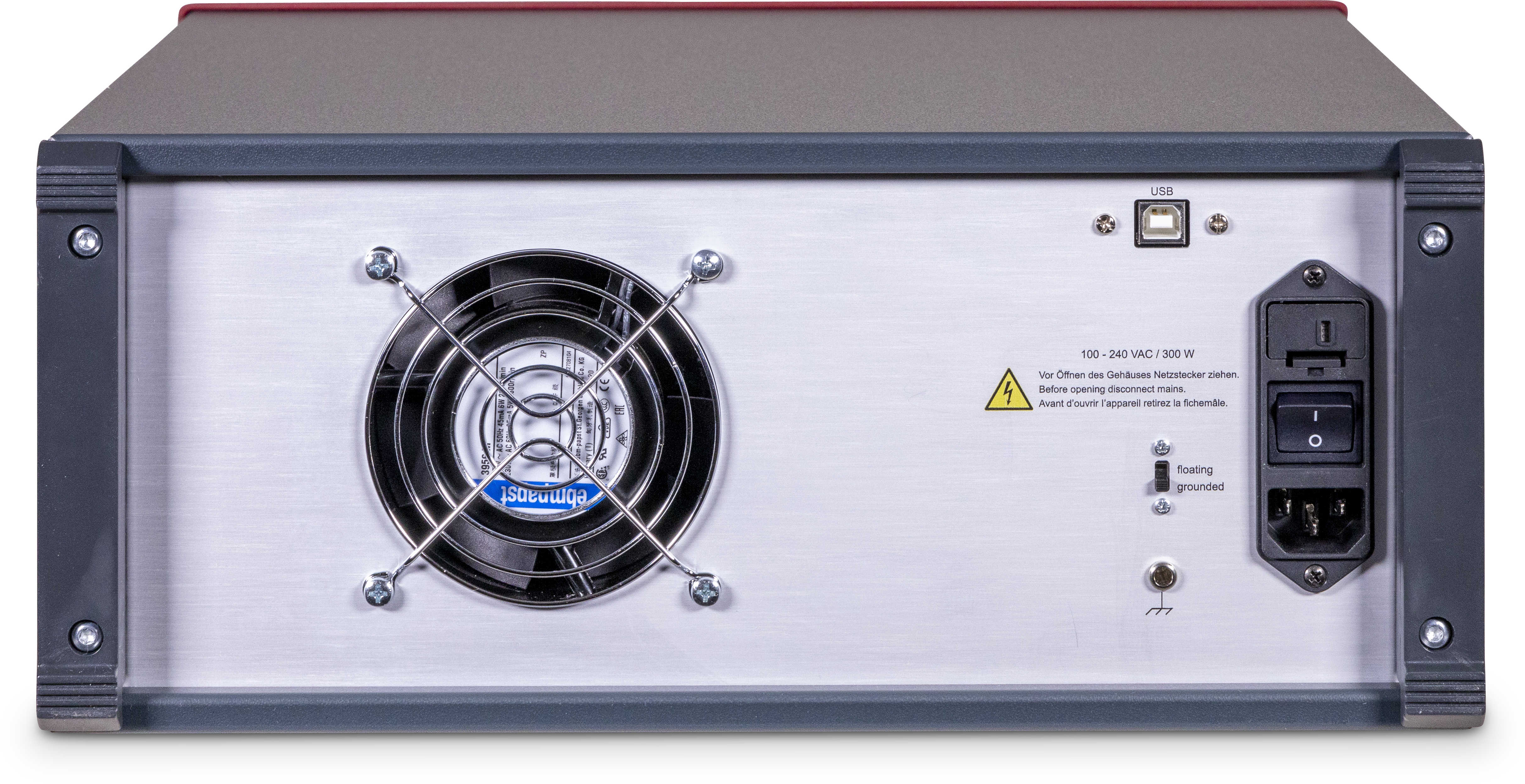
Fig. 3: Back panel of ZENNIUM potentiostat.
On the right side of the back panel, a USB connection is provided to connect the USB cable to the potentiostat.

Fig. 3: Back panel of ZENNIUM potentiostat.
1.2.1 Correct power settings
On the rightmost side of Fig. 3, a power cable connection and power switch are present. On top of the switch, a fuse is installed.
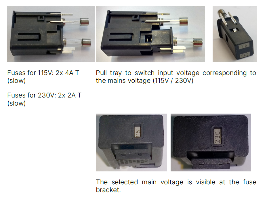
The number on the fuse bracket must be the same as the mains voltage in your geographical location (i.e., 115 V or 230 V). If that is not the case then you must correctly install the fuse.
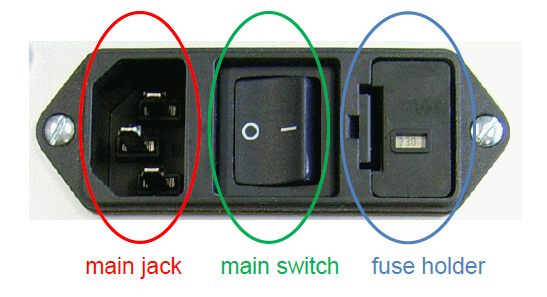
Don’t remove the fuse, if the power cable is connected and the potentiostat is turned on. To remove the fuse, push the snap-in nose to release the fuse bracket. This will pop out the fuse holder, take the fuse holder out and remove the fuse as shown in the image below. Reposition the fuse in such a way that the fuse holder shows the correct mains voltage for your geographical location.
1.2.2 Grounding/Floating setting
Fig. 3 shows the grounding/floating switch at the back panel of the ZENNIUM series potentiostat. This switch defines if the potentiostat is grounded or at floating conditions.
Grounding: If the device under test is at floating conditions, then the ZENNIUM series potentiostat must be grounded. For this, turn the switch at the back panel of potentiostat to “Grounded”. The ZENNIUM series potentiostats are grounded via the power cable of the potentiostat.
Floating: If the device under test is at grounding conditions, then the ZENNIUM series potentiostat must be at floating conditions. For this turn, the switch at the back panel of potentiostat to the “floating”.
Use Testbox only in ground mode. Using Testbox in floating mode will lead to erroneous results.
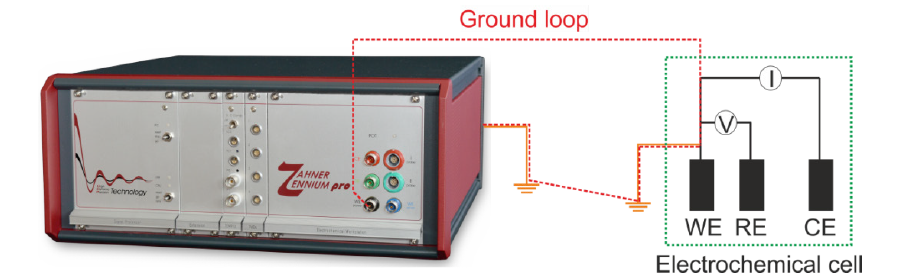
1.2.2.1 Ground loop
When both the potentiostat and the device under test are connected to the ground then a ground loop will be generated. In this configuration, electrical current from the potentiostat will not go to the device under test but will flow through this ground loop, leading to erroneous results. Fig. 6 shows the formation of the ground loop when the working electrode in an electrochemical cell and the potentiostat both are at the ground conditions.
1.2.2.2 Grounding of Faraday cage / ESD-matt
The 4-mm banana plug (marked in the image below) may be used to extend the grounding of the ZENNIUM series potentiostat to Faraday cage or ESD-matt. For grounding the Faraday cage/ESD-matt, connect it with a wire and plug the wire into the 4 mm banana plug.
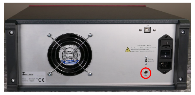
Do not additionally ground the potentiostat using the 4-mm banana plug. This will lead to a ground loop and will decrease the signal to noise ratio.